|
🛈NOTE
|
Originally published at https://marsik.codeberg.page/godox-olympus-protocol-article/ |
|
🗪 QUESTIONS
|
Discuss using any Fediverse account by responding to my Mastodon post https://witter.cz/@marsik/115480309138821664 |
I returned to photography after a few years' pause and discovered how much the technology had leaped forward. Affordable, well-built, and powerful cross-brand flash trigger technology has emerged in recent years.
Unfortunately, Olympus flashes are not supported by the X1R receiver devices, even though an X1R-O variant is mentioned in one of the manuals.
Since I own several fully functional Olympus flashes, I decided to draw upon my other hobby—amateur radio and electronics—to determine whether I could build a suitable receiver myself.
Reverse engineering a communication protocol involves considerable guesswork, particularly when two protocols must be decoded simultaneously. However, with systematic investigation and some educated guesses, certain findings uncover additional information that leads to further discoveries. I do not claim that all discoveries presented here follow purely rational pathways; serendipity [1] and fortunate guesses played their part in this process.
Disclaimers
Before presenting the results, I believe a few words about the legal aspects are necessary.
Multiple sources from both United States and European Union jurisdictions support the legality of reverse engineering in general.
The key takeaway from these sources is that reverse engineering for interoperability purposes is generally legal, while disassembly presents more complex legal considerations.
|
🛈NOTE
|
I declare that all information in this document was obtained from publicly available sources, or through analysis of emitted radio frequency and electrical signals. I made no attempts to access internal firmware in binary or source form (disassembly) of any device under test. |
|
🛈NOTE
|
I performed all work within the jurisdiction of the Czech Republic and the European Union, using devices and tools I purchased with my own funds. I received no sponsorship or financial support of any kind for this work. |
|
🛈NOTE
|
Product names mentioned in this text may contain registered trademarks. I am not affiliated with the companies owning these trademarks and use them solely to reference products by their official names. |
Godox X
All recent Godox devices use a 2.4 GHz protocol. How does one analyze a protocol like this? The following sections describe my step-by-step approach.
Officially published information
I began with the principle that reverse engineering should always start with official documentation and manuals.
One of the newest transmitters is the X3Pro (https://www.godox.com/product-e/X3Pro.html).
The product page confirms what I already knew:
Wirelessly trigger Canon, Nikon, and Sony flashes with full TTL support…
As expected, there is no Olympus support in the receiver device line.
Several pieces of summary information are scattered throughout the product pages and manuals. The devices support 32 different channels and up to 16 different flash groups. While noteworthy, this information alone was not particularly useful for protocol analysis.
However, I found several interesting details in the manual chapter about shooting modes. The so-called "All-shoot" mode allows multiple transmitters to share the same flashes with no extra configuration beyond the channel number. This indicates there is no device pairing or transmitter-specific encryption.
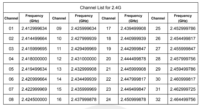
I also discovered a compatibility mode with the Sekonic L-858 light meter, which suggested I might find additional information in the Sekonic manual. That manual references the RT-GX Godox-compatible module, and chapter 5 contains a channel table with corresponding frequencies.
Public information sources
All electronic devices must disclose certain information to government regulators such as the FCC in the United States.
Another valuable source of information consists of YouTube videos and blogs where enthusiasts open devices and post photographs of their internal components.
FCC
All Godox devices registered with the FCC are listed at https://fccid.io/2ABYN.
The specific device I intended to use as a transmitter was the XProII, though any recent transmitter model would suffice for this analysis.
The XProII device materials are available at https://fccid.io/2ABYN060. I was primarily interested in the internal photographs to learn about the hardware implementation and in the test report. The XProII contains two transmitting devices: one for Bluetooth and one for the Godox protocol.
The test report (https://fccid.io/2ABYN060/Test-Report/Test-Report-6112981) reveals the first crucial piece of information on page 7.
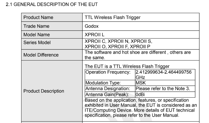
From this table, I learned that the operating frequency range is 2.412999634–2.464499756 GHz and the modulation scheme is MSK (Minimum Shift Keying).
A detailed frequency table on the next page shows the center frequency of all Godox channels. This information corroborates what I had already found in the Sekonic manual.
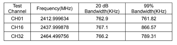
The 20 dB bandwidth of the signal is documented on page 31.
Unfortunately, the internal photographs were somewhat blurred, and the hardware component markings were not sufficiently readable. I needed to search for better photographs from alternative sources.
Teardowns
With basic information about frequencies and modulation in hand, I wanted to determine what hardware modules could be used to receive or transmit such signals. The FCC photographs were insufficient, but fortunately, searching uncovered a much richer source:
The photographs reveal the internal design, which is actually quite straightforward. The device uses a Cortex-M based microcontroller (Geehy F072), which was not my primary concern. More importantly, the radio transceiver is the Texas Instruments CC2500.
The CC2500 datasheet proved essential for further analysis. A brief note in section 16.2 on page 34 is crucial for the subsequent sections that employ software-defined radio to decode the signal.
The MSK modulation format implemented in CC2500 inverts the sync word and data compared to e.g. signal generators.
The datasheet also describes how synchronization and signal detection are implemented. The CC2500 first transmits alternating preamble bits (0xAA), followed by 2 bytes [Sync1 Sync2], possibly repeated as [Sync1 Sync2 Sync1 Sync2].
At this stage, whether data whitening or CRC are part of the signal remained to be determined. The radio chip itself provides no built-in encryption support.
Spectrum analysis
Before purchasing any additional hardware or chips, I decided to put my HackRF One to good use. This software-defined radio can receive (and transmit) signals in the necessary frequency range.
I conducted my first examination using the Gqrx software-defined radio receiver.
Some adjustment of the sample rate and processing speed was required because the signals appeared to be quite brief.
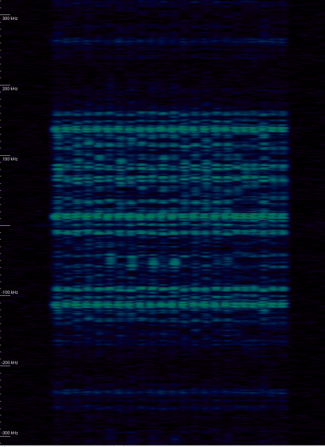
The spectrum appears as follows:
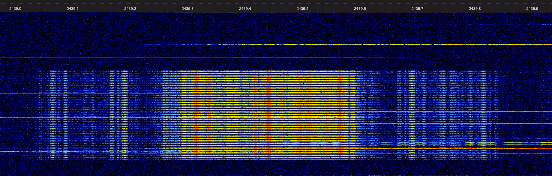
The spectrum already reveals interesting information. The MSK Wikipedia article describes a relationship between the frequency peaks and the symbol rate:
The maximum frequency deviation is δ = 0.5 fm where fm is the maximum modulating frequency.
The strongest peaks at the edges of the main spectrum block are precisely 250 kHz apart, which likely corresponds to the data rate.
With this information, I had sufficient knowledge to attempt building a receiver.
GNU Radio receiver
To confirm my findings, I constructed a simple decoder using GNU Radio. GNU Radio Companion makes it relatively straightforward to connect signal processing blocks and experiment with various radio modulation parameters.
Here is what I constructed (the final solution; blocks I used during the exploratory phase are left disabled):
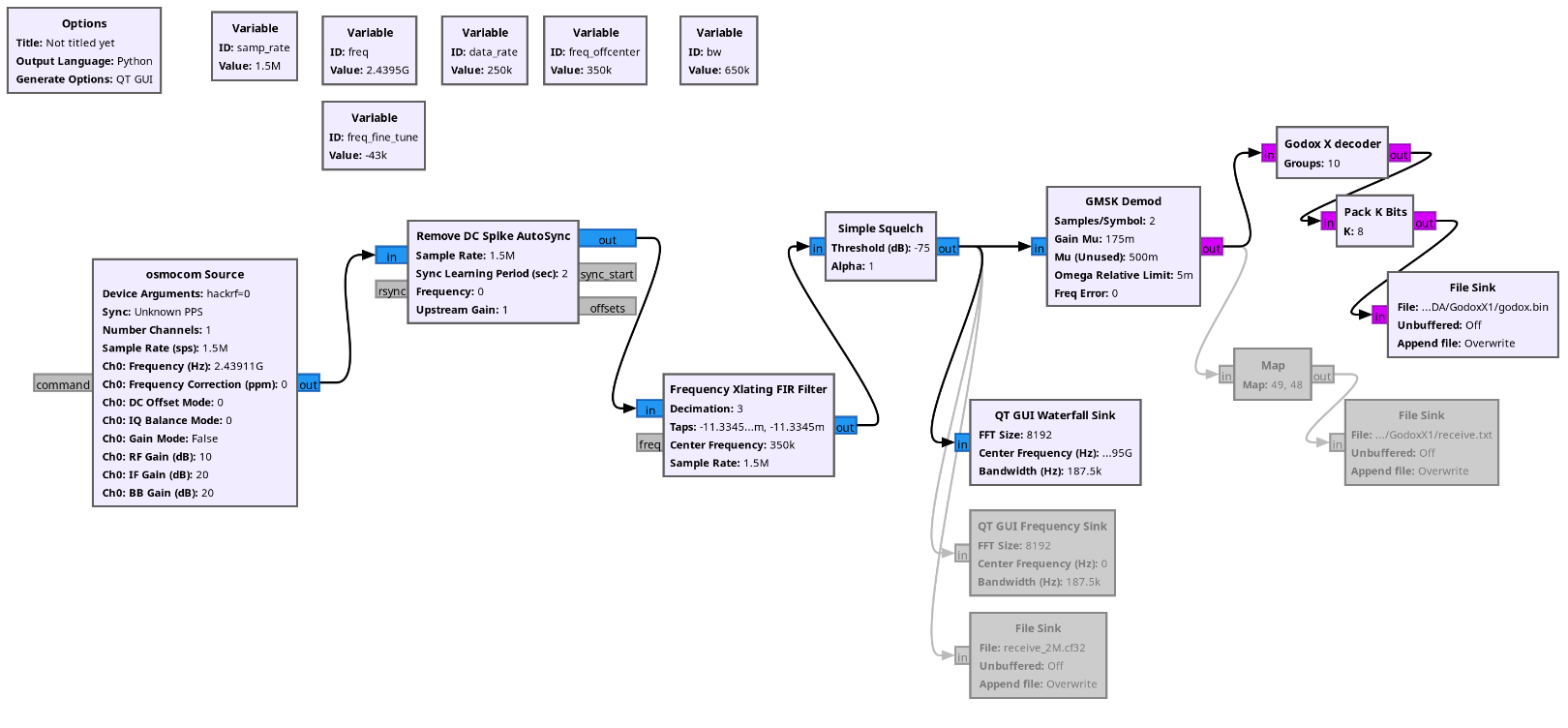
I used file sink blocks to dump the raw bitstream (inverted according to the CC2500 datasheet) to a file and then searched for synchronization patterns.
Since there are no byte boundaries in the raw bitstream, this analysis was somewhat challenging. However, I could search for sequences of 10101010 (or the inverted version) to identify candidate messages.
I found a consistent byte pattern following the preamble: 1100001101101000 (0xC3 0x68).
I performed a simple analysis using bash to estimate message length. By varying the prefix length used by the uniq command for comparison and observing the number of matching messages, I determined that messages were relatively short (prefixes longer than 4 bytes showed insufficient repetition).
sed -e "s/1100001101101000/\n1100001101101000 /g" <receive.txt >receive-ml.txt
sort receive-ml.txt | uniq -d -w 68 -c | sort -n
I implemented the decoder as a custom Python block that searches for the sync pattern. It successfully receives consistent byte sequences each time I press the test trigger button on the Godox transmitter.
I observed a clear pattern in the commands, though I noticed slight variations in the command set received with each attempt. The GNU Radio flowgraph could not reliably receive and decode all messages consistently, and my GNU Radio expertise was insufficient to resolve this issue. However, I am more proficient with hardware electronics.
Godox X1T-S PCB analysis
I was reluctant to damage my new transmitter, but an opportunity arose to purchase a used Godox X1T-S transmitter at a very low price. According to its documentation, this model is compatible with the Godox X 2.4 GHz protocol, and photographs on the FCC website confirm it uses the same hardware design.
Having conducted reverse engineering projects previously, I had several tools available to assist with this analysis.
First, I had a hardware analysis rig. I 3D-printed a platform with probe needles based on the PCB Workstation with Nano-Probes design. My needles were somewhat cruder than the original design, but they proved adequate for this task.
Using the CC2500 datasheet to identify the control pins, I located them on the X1T-S PCB and determined the optimal probing points.
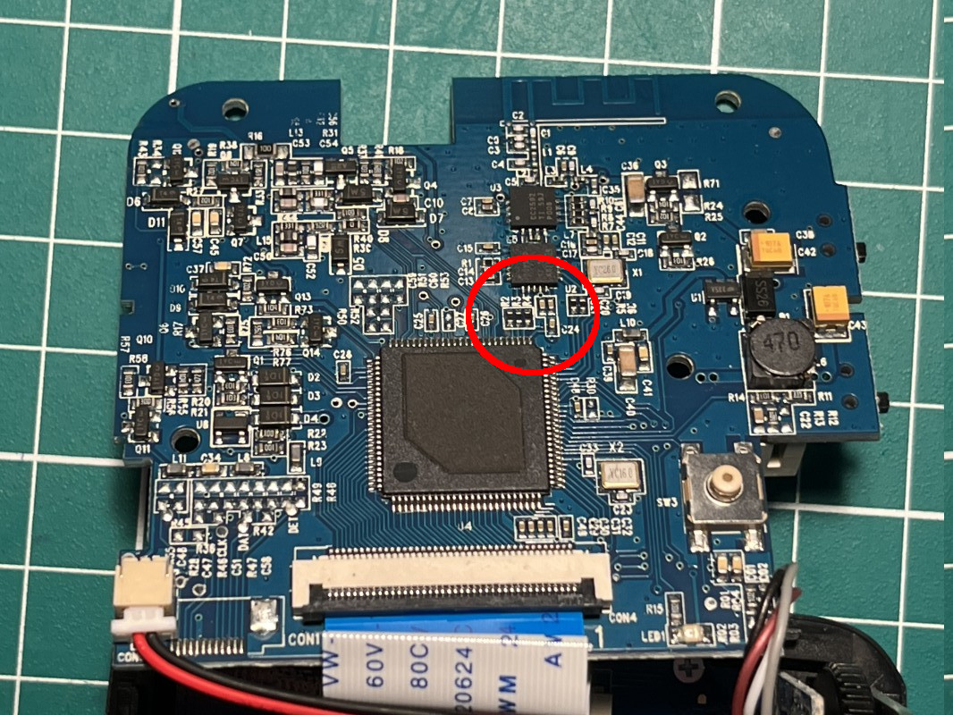
Fortunately, the device employs current-limiting resistors for all SPI-related traces, which served as excellent targets for the probe needles.
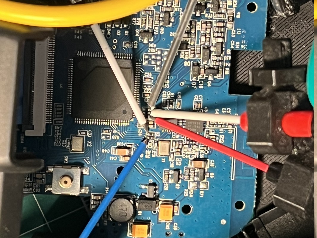
I connected this setup to a logic analyzer, configured the SPI decoders, and monitored the communication between the CC2500 and the main CPU.
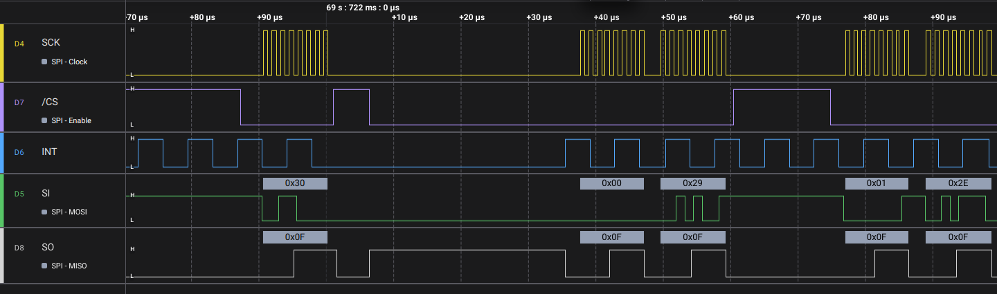
The analysis confirmed my earlier suspicions. The frequency, bandwidth, and sync words matched expectations, as did the data bitrate. I also confirmed that packets are 4 bytes in length.
CC2500 receiver
While the SPI probe rig worked well, it was somewhat unwieldy and prone to connection issues when disturbed. In short, the probe needles did not maintain reliable contact, I tended to bump the setup, and there were too many wires cluttering my workspace.
The time had come to build a dedicated hardware receiver. Unfortunately, fully functional CC2500-based modules are not readily available locally, and I lacked the patience to design and fabricate a module from scratch (including all the necessary filtering and RF components).
I found an online shop in the Netherlands with available modules and purchased several: tinytronics.nl. While probably not the most economical solution, it was the fastest.
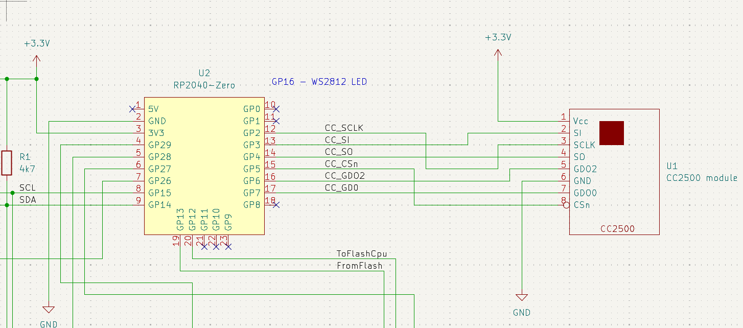
I needed a microcontroller capable of handling the protocol’s speed requirements. My usual microcontroller choices were marginally too slow for the required SPI speed, so I selected an inexpensive RP2040 module. I implemented a simple receiver that forwarded all Godox protocol bytes over USB to my computer.
Godox XProII message analysis
With the receiver operational, it was time to record and analyze various message types. I used the XProII transmitter, systematically selecting different groups, modes, and functions while observing the resulting messages.
Manual power settings, modeling lamps, and beepers were straightforward to decode. However, the trigger sequences proved more complex.
Although I present the Godox analysis first in this document, I actually analyzed both the Godox and Olympus protocols simultaneously to correlate timing relationships.
The test setup became quite cluttered during this phase. You may also notice I used a different RP2040 board (a Challenger RP2040 LTE Mk.II) in the photographs. I work on multiple projects and simply used available hardware before I finalized my selection of the final CPU.
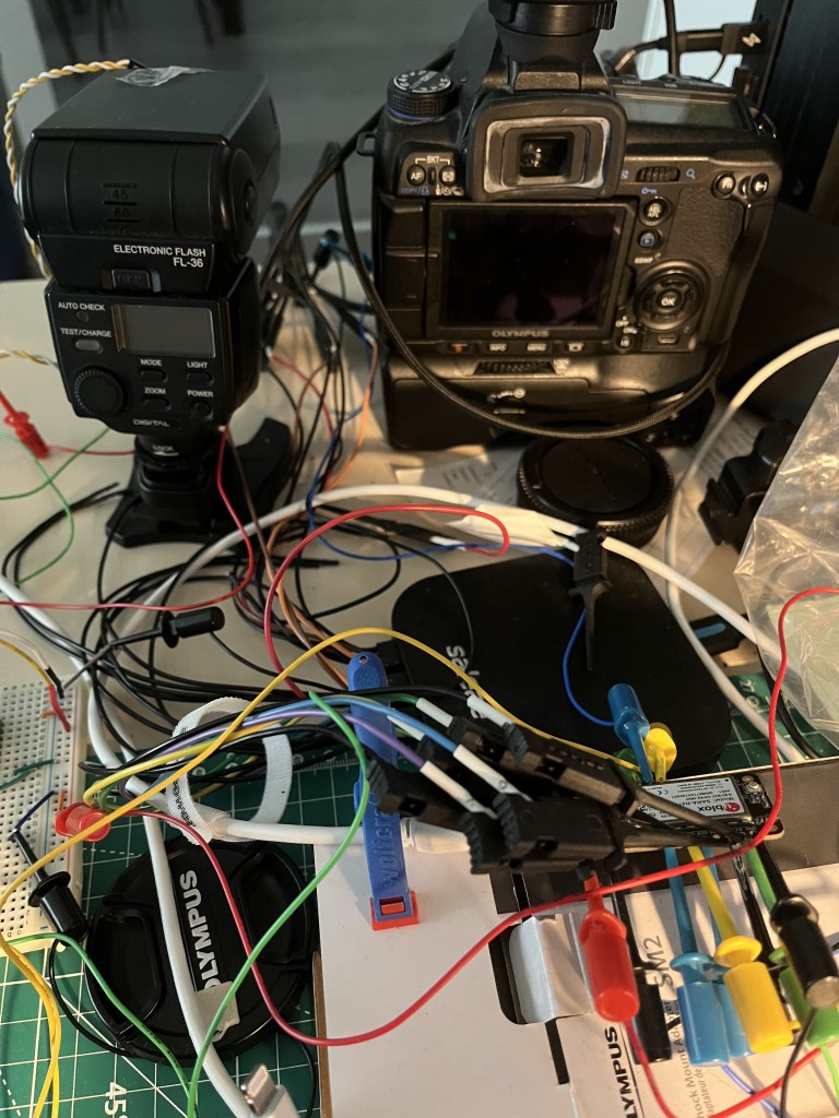
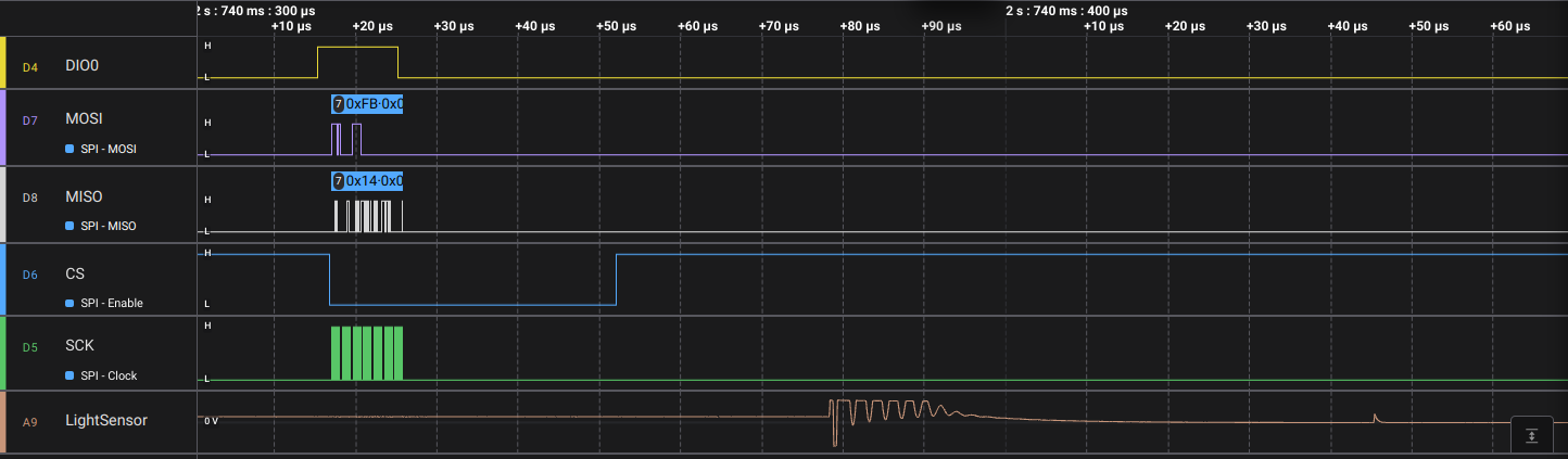
To decode the trigger commands, I used the cabling from my Olympus analysis (described in a later section) and constructed a simple photodiode sensor—merely a photodiode that shorted a pull-up resistor to ground—which I attached to the flash head. I then used my logic analyzer to simultaneously record the camera commands to the Godox transmitter, the received radio commands on the CC2500 side, and the analog voltage levels from the photodiode.
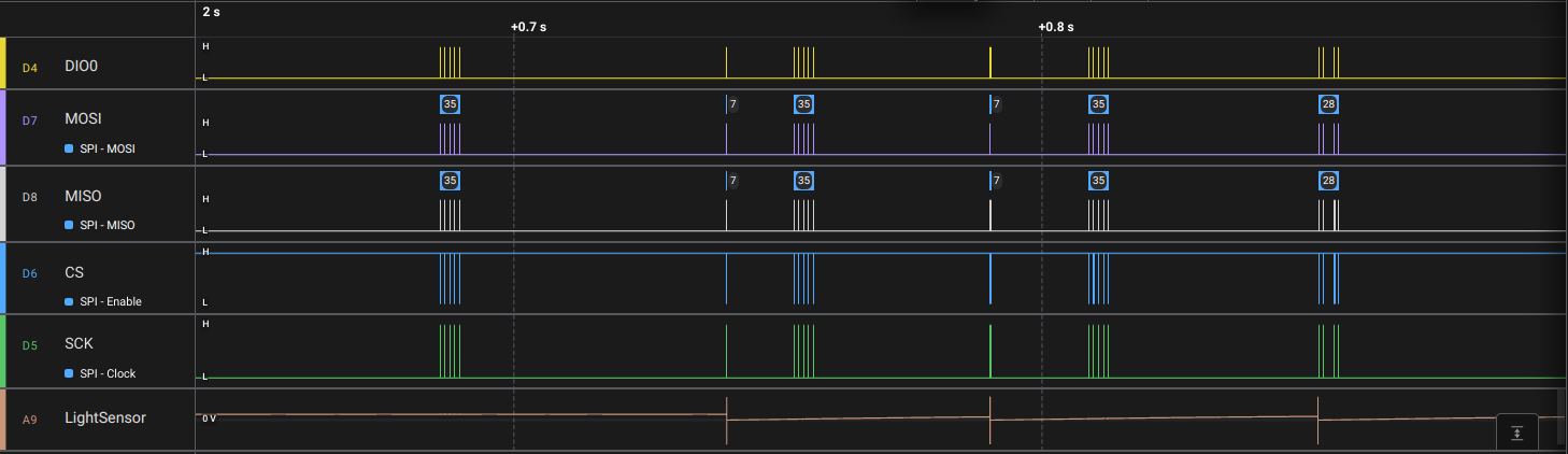
The photodiode setup was not ideal; the flash generated significant electrical noise during capacitor charging, and the voltage drop during firing was smaller than desired. Nevertheless, it proved sufficient for identifying flash firing events.
During this testing phase, I also needed to determine how power levels are encoded. I systematically increased the manual power by 1/3 EV increments, recorded each message, and repeated this across the entire range (−3 EV to +3 EV). This revealed that Godox employs 1/10th of a stop resolution.
Godox X protocol reference
The following is a comprehensive list of all messages I identified and decoded.
|
Warning
|
No warranty is provided regarding the accuracy or completeness of this information. |
Flash groups receive their configuration as 4-byte messages. The flashes do not send acknowledgements.
[0xA9, group, setting, value]
where group is 0xA, 0xB, 0xC, …, 0xE for the standard 6 groups and 0xF, 0x1, 0x2, …, 0x0 for the additional 10 groups.
Configuration can also be broadcast to all groups simultaneously. This is primarily used for TTL triggers, which I describe later.
Broadcast transmissions use a special group code of 0x50.
[0xA9, 0x50, setting, value]
In addition to group-specific commands, global short commands exist. These trigger messages utilize only two meaningful bytes, although they are received into the same 4-byte buffer.
[0xD5, trigger_code, x, x]
The various settings I identified are:
Prepare / reset
[0xA9, 0x50, 0xC0, 0x4]
I observed this command during TTL trigger sequences. I believe it signals a reset operation to enable clean configuration of subsequent flash power and mode settings.
TTL vs manual vs multi mode
[0xA9, group, 0xB1, mode]
The mode field accepts three values.
A value of 0x0 sets the flash to TTL mode (and enables it).
Conversely, 0x1 sets the flash to manual mode. Manual mode (0x1) combined with power value 0xFF disables the flash group.
The value of 0x2 sets the groups to the multi strobe mode. Multi mode (0x2) combined with power value 0xFF disables the flash group.
Flash manual power
[0xA9, group, 0xBC, power]
The power field controls power reduction from full output. The value 0x00 represents full power (1/1), and each increment of 10 (0x0A) reduces power by one EV stop. Thus, 0x0A is half power, 0x14 (20 decimal) is 1/4 power, etc. A disabled group is indicated by setting power to 0xFF.
TTL power
[0xA9, group, 0xB9, power]
This is an alternative power setting used in TTL mode. Unlike manual power mode, higher values represent higher power output.
Godox uses the value 0x2D to represent the minimum pre-flash power reported by Olympus speedlights. I describe how this was determined in the Olympus analysis section.
As in manual mode, each 0x0A (10 decimal) units represents one EV stop.
Zoom
[0xA9, group, 0xB2, zoom_mm]
This command controls the flash zoom head position. The zoom_mm field specifies the focal length in millimeters. The value represents 35 mm camera equivalent focal lengths. Thus, a 10 mm Olympus (Micro Four Thirds) focal length is transmitted as 20 mm.
High speed sync enable
[0xA9, group, 0xB3, hss]
The hss value enables (0x1) or disables (0x0) the high speed sync mode.
Selective trigger prepare
[0xA9, 0x50, 0xB4, 0x02]
This command is issued before the following trigger command. It allows the receiver to issue any preparatory commands.
Selective trigger fire
[0xA9, 0x50, 0xB4, 0x01]
This command is used to issue a TTL preflash fire command.
Flash manual power for multi mode
[0xA9, group, 0xBD, power]
The power field controls power reduction from full output. The value 0x00 represents full power (1/1), and each increment of 10 (0x0A) reduces power by one EV stop. Thus, 0x0A is half power, 0x14 (20 decimal) is 1/4 power, etc. A disabled group is indicated by setting power to 0xFF.
Multi mode pulse count
[0xA9, 0x50, 0xBE, count]
Controls the multi mode pulse count.
Multi mode pulse frequency
[0xA9, 0x50, 0xBF, frequency_hz]
Controls the multi mode pulse frequency. As the variable name suggests, the value is in Hz.
Modeling lamp enable
[0xA9, group, 0xD3, enable]
The enable field controls whether the modeling lamp is active for this specific group. A value of 0x1 indicates ON, while 0x00 indicates OFF.
Note that both the per-group setting and the global modeling lamp enable (described in the trigger messages section) must be set to ON for the lamp to illuminate.
Modeling lamp proportional control
[0xA9, group, 0xD6, proportional]
When proportional is set to 0x1, the manual power setting is ignored, and the modeling lamp power is automatically derived from the flash power setting.
Modeling lamp manual power
[0xA9, group, 0xD1, power_pct]
The power_pct field controls the modeling lamp output as a percentage of full power. The valid range is 0x00 to 0x64 (0 to 100 decimal).
Enable flash beep globally
[0xD5, 0x81, x, x]
Enable beep signal for all flashes.
Disable flash beep globally
[0xD5, 0x80, x, x]
Disable beep signal for all flashes.
Enable modeling lamp globally
[0xD5, 0x81, x, x]
Globally enable modeling lamp control.
Disable modeling lamp globally
[0xD5, 0x80, x, x]
Globally disable all modelling lamps.
Trigger with manual power
[0xD5, 0x11, x, x]
This is the manual trigger fire command. Fire the flash using the configured manual power.
Trigger with manual power in legacy hot shoe mode
[0xD5, 0x09, x, x]
This is the manual trigger fire command. Fire the flash using the configured manual power.
Final trigger with TTL power
[0xD5, 0x19, x, x]
This is the final TTL trigger fire command. Fire the flash using the configured TTL power.
Trigger release
[0xD5, 0x21, x, x]
This command releases the trigger.
Protocol examples
TTL trigger of group A
0xA9, 0x50, 0xC0, 0x04
0xA9, 0x0A, 0xB1, 0x00
0xA9, 0x50, 0xB3, 0x00
0xA9, 0x0A, 0xB9, 0x2D
0xA9, 0x50, 0xB4, 0x02
0xA9, 0x50, 0xB4, 0x01
pre-flash fired
0xA9, 0x50, 0xC0, 0x04
0xA9, 0x0A, 0xB1, 0x00
0xA9, 0x50, 0xB3, 0x00
0xA9, 0x0A, 0xB9, 0x41
0xA9, 0x50, 0xB4, 0x02
0xA9, 0x50, 0xB4, 0x01
pre-flash fired
0xA9, 0x50, 0xC0, 0x04
0xA9, 0x0A, 0xB1, 0x00
0xA9, 0x50, 0xB3, 0x00
0xA9, 0x0A, 0xB9, 0x6E
0xA9, 0x50, 0xB4, 0x02
0xD5, 0x19, 0xFF, 0x7F
0xD5, 0x19, 0x8F, 0xFF
main flash fired
0xD5, 0x21, 0xF3, 0xF8
0xD5, 0x21, 0xFF, 0xFF
Manual power trigger of group A
0xA9, 0x50, 0xC0, 0x04
0xA9, 0x50, 0xB3, 0x00
0xA9, 0x50, 0xB4, 0x02
0xA9, 0x50, 0xC0, 0x04
0xA9, 0x50, 0xB3, 0x00
0xA9, 0x50, 0xB4, 0x02
0xA9, 0x50, 0xC0, 0x04
0xA9, 0x50, 0xB3, 0x00
0xA9, 0x50, 0xB4, 0x02
0xD5, 0x19, 0xFF, 0xFC
0xD5, 0x19, 0xEF, 0xFF
main flash fired
0xD5, 0x21, 0xE7, 0xEB
0xD5, 0x21, 0xFB, 0xFA
Configure manual power of group A
From 1/128 to 1/256 in 1/10th of a stop steps.
0xA9, 0x0A, 0xBC, 0x47
0xA9, 0x0A, 0xBC, 0x48
0xA9, 0x0A, 0xBC, 0x49
0xA9, 0x0A, 0xBC, 0x4A
0xA9, 0x0A, 0xBC, 0x4B
0xA9, 0x0A, 0xBC, 0x4C
0xA9, 0x0A, 0xBC, 0x4D
0xA9, 0x0A, 0xBC, 0x4E
0xA9, 0x0A, 0xBC, 0x4F
0xA9, 0x0A, 0xBC, 0x50
Turn group A off
0xA9, 0x0A, 0xB1, 0x01
0xA9, 0x0A, 0xBC, 0xFF
Switch group A to TTL
0xA9, 0x0A, 0xB1, 0x00
0xA9, 0x0A, 0xBC, 0xFF
Olympus TTL
With the Godox protocol understood, the next step was to determine how to use it to control the target speedlight: the Olympus FL-36®.
(As noted earlier, this sequential presentation is somewhat simplified for clarity. In practice, I analyzed both protocols simultaneously, refining my understanding of each through their correlation—particularly regarding power level encoding.)
Physical interface
The Olympus hot shoe uses the ISO standard center trigger contact plus four additional smaller contacts positioned identically to Canon hot shoes (though with different functions).
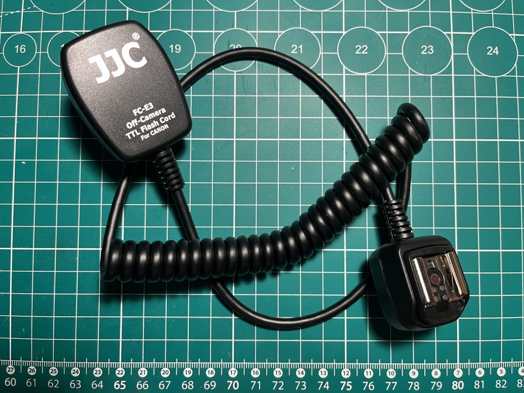
Fortuitously, a Canon extension cable can be used for off-camera operation of Olympus speedlights, which would later allow me to intercept the protocol communication by opening the cable.
Electrical analysis
I began with simple multimeter measurements of each pin relative to ground.
For orientation, the following description refers to the side with the safety pin hole as the "top side." I conducted all tests with an aging Olympus E-30 DSLR to avoid any risk of damaging my newer camera bodies.
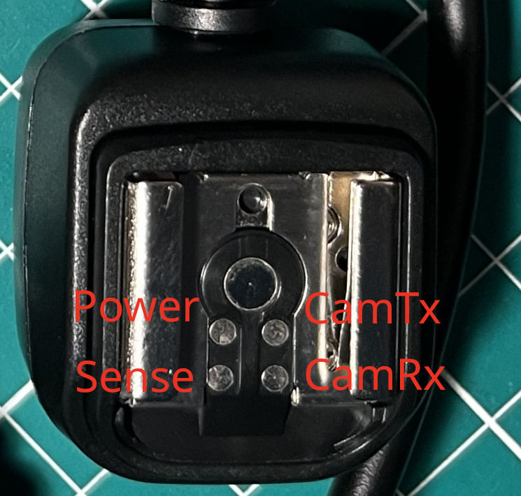
While the photograph shows the pin functions, I determined those later. Initially, I focused solely on electrical characteristics.
The bottom right camera pin measured 3.3 V with a short-circuit current of 313 µA, suggesting a 10 kΩ pull-up resistor.
The top right camera pin showed no voltage, but the corresponding FL-36 flash pin measured 5 V with 100 µA short-circuit current (indicating a 50 kΩ pull-up).
The bottom left pin and the center trigger pin exhibited identical characteristics: 5 V and 100 µA on the flash unit.
The top left power pin is present only on newer camera models. Older models provide only the communication and sense pins.
Link-level protocol
I cut open the extension cable to expose the inner wires.
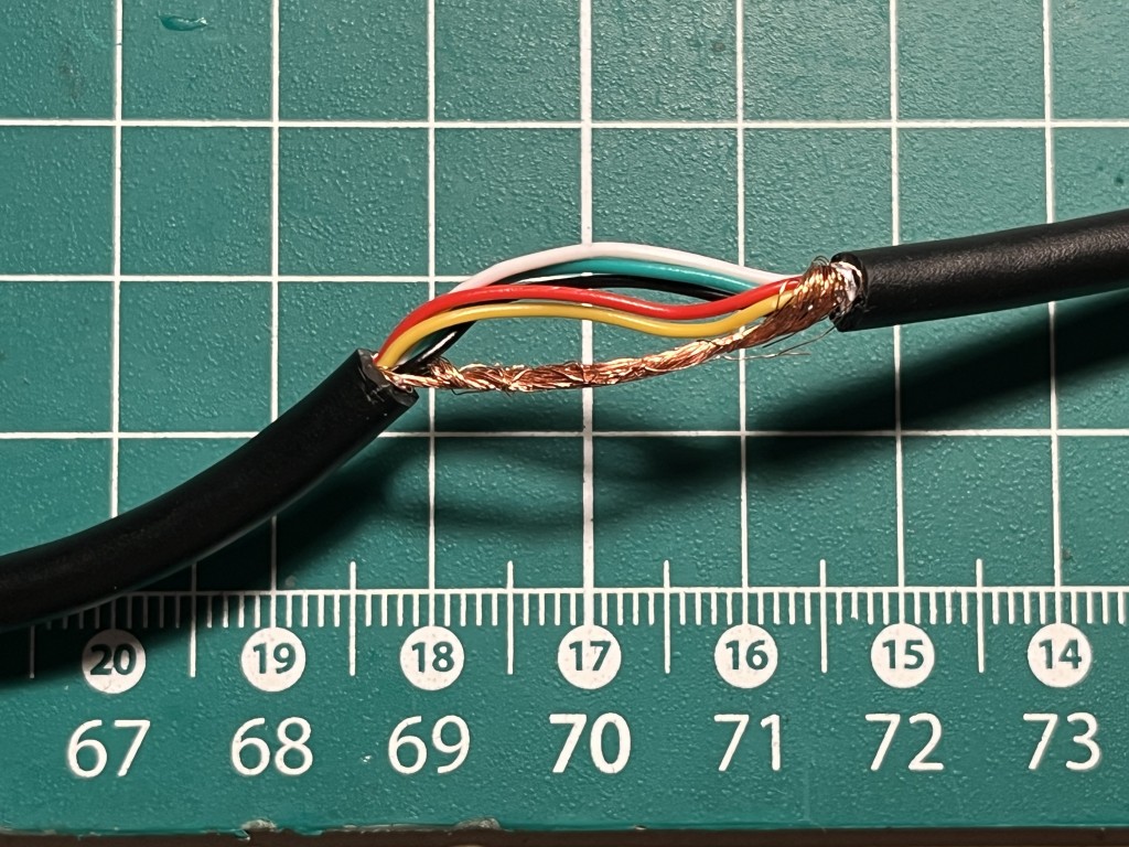
I then attached a breakout connector (2×3 pin) to create a more reliable measurement setup and connected the logic analyzer probes to observe the communication.
This specific cable model (I have three identical units) uses the shield for ground and employs the following wire color assignments:
-
White: Power
-
Red: CameraRx (flash to camera)
-
Yellow: Trigger center pin
-
Black: CameraTx (camera to flash)
-
Green: Sense
The camera communicates using a full-duplex asynchronous serial protocol at 20,800 baud with standard 8N1 configuration (8 data bits, no parity, 1 stop bit).
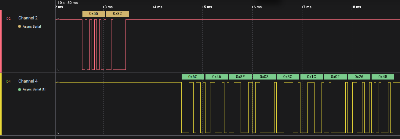
All signaling employs open-drain connections. The receiving side provides a pull-up resistor to its own logic high voltage, while the sending side pulls the line to ground to transmit a logic zero. This architecture applies to all signals, including the trigger.
Protocol analysis
Decoding the Olympus TTL protocol proved more challenging than the Godox protocol.
I collected hundreds of protocol exchange samples while systematically varying camera and flash settings. I methodically modified shooting modes, shutter speeds, apertures, flash head zoom positions, camera focal lengths, exposure compensation settings, and—critically—flash exposure compensation both on the camera and on the flash unit itself.
I also collected maximum flash power samples by recording TTL mode exchanges with the lens cap attached (producing completely dark frames). I tested this configuration across various apertures and zoom levels.
This flash power testing revealed the checksum pattern. The 0x03 command was brief, and modifying power levels consistently altered two "parameter" bytes rather than one. These two bytes invariably differed by 0x03. This was speculative reasoning, but it proved correct. I then applied the same hypothesis to the 0x87 command, which also matched. Extending this pattern to the 0x82 command required only moments.
Next, I attempted to locate power level information in the flash’s status responses. I discovered that the first pre-flash power consistently matched the lower 7 bits of byte 2, while the main flash power matched the lower 7 bits of byte 1 in the 0x82 command response. (This correlation took considerable time to identify.)
I repeated this analysis with the flash in high-speed sync mode and found analogous behavior, but using byte 4. The high speed sync mode triggers a long burst sequence and while the maximal reported power changes with shutter speed, the flash burst is always about 8 milliseconds long.
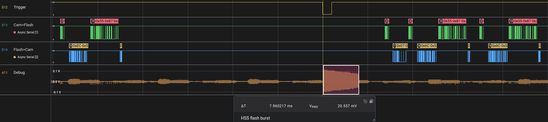
I also conducted power tests with the lens cap removed, using a gray cloth as a target. This revealed that camera-side flash exposure compensation can reduce flash power below the value stored in byte 2 (the first pre-flash value). This led me to conclude that the first pre-flash uses a fixed power level (likely 1/128 of maximum), though the flash is capable of even lower output.
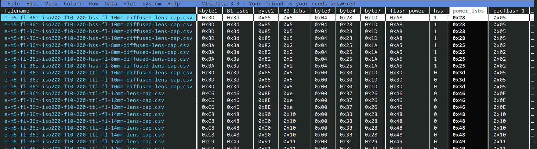
Analyzing this substantial dataset required robust data analysis tools supporting computed columns, frequency analysis, filtering, and bit manipulation. While LibreOffice provided a reasonable starting point, VisiData proved far more powerful. I highly recommend it for anyone analyzing multiple datasets, particularly if you know Python.
Protocol reference
|
Warning
|
No guarantee is provided regarding the correctness or accuracy of this analysis. Several interpretations are based on educated guesses that appear correct but may be partially or significantly inaccurate. |
The camera initiates all exchanges by transmitting what is likely a baud rate calibration byte: 0x55. It then sends a command byte, optional parameter bytes, and sometimes a checksum byte.
I have identified several commands that my Olympus cameras employ.
0x82 Flash status query
Camera sends: [0x55, 0x82]
The flash responds with 9 bytes: [B0, B1, …, B7, CHSUM].
The CHSUM is calculated as the lowest 8 bits of the sum of all command bytes (excluding the 0x55 preamble) plus all response bytes.
This command is transmitted frequently. The Olympus E-30 sends it every 300 milliseconds.
-
B0[7]bit (the most significant bit) is the "charged and ready" status -
B0[6..4]flash mode - 0x0 TTL modes (TTL and FP TTL), 0x6 manual modes (including FP), 0x4 auto mode -
B0[3..0]always 0xC -
B1[7]is set to 1 when the flash is pointing forward or slightly down, 0 in all other directions. -
B1[6..0]maximum power level for the 0x03 trigger flash command -
B2[6..0]first pre-flash power for 0x02 trigger flash command
The difference B1[6..0] - B2[6..0] is consistently 56, corresponding to 8 steps per EV × 7 EV (representing the range from 1/1 to 1/128 power).
-
B3[2]HSS enabled -
B4[7]indicates post-flash status, possibly a "good exposure" indicator -
B4[6..0]maximum power for high-speed sync (0x03 flash trigger). This value varies with shutter speed. This behavior matches the FL-36R manual (table on page 44). The Godox XProII always reports 0x46. -
B5function unknown, but varies with zoom setting and consistently equalsB4[6..0] - 0x20. The Godox XProII always reports 0x27. -
B6function unknown. Always 0x02 for FL-36R, 0x03 for Godox TT685II, and 0xE7 for Godox XProII. -
B7function unknown. Godox devices always report 0x00, while FL-36R always reportsB1[6..0] + 0x20.
0x86
Camera sends: [0x55, 0x86]
The flash responds with 7 bytes: [B0, B1, …, B5, CHSUM].
The CHSUM is calculated as the lowest 8 bits of the sum of all command bytes (excluding the 0x55 preamble) plus all response bytes.
The function of this command is unknown.
0x87 Camera TTL information
Camera sends: [0x55, 0x87, B0, B1, …, B9, CHSUM]
The flash responds with: [0x5A]
This command switches the flash to TTL mode when received for the first time. It conveys camera settings including shutter speed, focal length, aperture, and ISO.
-
B0- ISO - 0x20 = ISO 200, each 0x08 added increases ISO by 1 EV (0x18 = ISO 100, 0x28 = ISO 400, 0x30 = ISO 800) -
B1- aperture - 0xA0 = F4.0, each 0x08 added then closes the aperture by 1 EV (0xA8 = F5.6, 0xB0 = F8, 0xC0 = F16) -
B2- changes with zoom (14 mm and 15 mm = 0x33, 16 - 18 mm = 0x34, 19 - 20 mm = 0x35, 25 mm = 0x36, 30 mm = 0x37, 35 mm = 0x38, 42 mm = 0x39, 45 mm = 0x39, 108 mm = 0x3F - maximal value) -
B3- 0x1F before flash fires, 0x1C after flash fires, 0xDF when idle -
B4- does not change with zoom -
B5- camera side flash exposure compensation, 0x20 is 0 EV, each 0x08 added increases flash power by 1 EV (0x28 = +1 EV, 0x18 = -1 EV, 0x08 = -3 EV) -
B6- 0x01 before and right after flash fires, 0x3D when flash is idle -
B7- shutter speed - 0x00 = 1/60 s, each 0x10 shortens the time by 1 EV (0x10 = 1/125 s, 0x20 = 1/250 s), time longer than 1/60 s is always 0x00 -
B8- I believe this is some kind of summary exposure value, possibly used to show the ideal distance on the flash display. When in TTL mode with HSS disabled it seems to match the following formula:203 + flash max power (from 0x82 byte B1) - aperture (B1 here). When in high speed sync mode (both shutter speed > sync speed and flash in FP TTL mode) the formula is203 - 16 (0x10) + flash max power (from 0x82 byte B1) - aperture (B1 here). -
B9- same asB0
0x88
Camera sends: [0x55, 0x88]
The flash responds with 13 bytes: [B0, B1, …, B11, CHSUM].
The CHSUM is calculated as the lowest 8 bits of the sum of all command bytes (excluding the 0x55 preamble) plus all response bytes.
The function of this command is unknown.
0xD6
Camera sends: [0x55, 0xD6, 0x55, 0xAA]
The flash responds with 9 bytes: [B0, B1, …, B7, CHSUM].
The CHSUM is calculated as the lowest 8 bits of the sum of all command bytes (excluding the first 0x55 preamble) plus all response bytes.
I observed this command only during the initial flash interrogation by the camera. It is not repeated subsequently.
The function of this command is unknown.
0xD7
Camera sends: [0x55, 0xD7, 0x55, 0xAA]
The flash responds with 5 bytes: [B0, B1, …, B4, CHSUM].
The CHSUM is calculated as the lowest 8 bits of the sum of all command bytes (excluding the first 0x55 preamble) plus all response bytes.
I observed this command only during the initial flash interrogation by the camera. It is not repeated subsequently.
The function of this command is unknown.
0xD8
Camera sends: [0x55, 0xD8, 0x55, 0xAA]
The flash responds with 5 bytes: [B0, B1, …, B4, CHSUM].
The CHSUM is calculated as the lowest 8 bits of the sum of all command bytes (excluding the first 0x55 preamble) plus all response bytes.
I observed this command only during the initial flash interrogation by the camera. It is not repeated subsequently.
The function of this command is unknown.
0x02 Pre-flash power
Camera sends: [0x55, 0x02, power, CHSUM]
The flash responds with: [0x5A]
The CHSUM is calculated as the lowest 8 bits of the sum of all command bytes (excluding the 0x55 preamble).
The first pre-flash power value consistently matches B2[6..0] from the 0x82 status query response.
The second pre-flash power is always 0x10 higher than the first (16 decimal, equivalent to 2 EV).
0x03 Main-flash power
Camera sends: [0x55, 0x03, power, CHSUM]
The flash responds with: [0x5A]
The CHSUM is calculated as the lowest 8 bits of the sum of all command bytes (excluding the 0x55 preamble).
Power increases by 0x08 per EV stop. I determined this relationship by observing the main flash power in TTL mode while varying the camera’s flash exposure compensation.
When bit power[7] (the most significant bit) is set, it indicates that high-speed sync flash is required.
Protocol examples
To control the flash programmatically, it must first be configured to one of the TTL modes (TTL or FP TTL).
The flash automatically switches to TTL mode upon receiving the Camera TTL information command (0x87) for the first time. It can also be manually set to TTL mode via the flash’s buttons, but only after the flash has already received TTL data from the camera.
Flash initialization
0x55	0x82
0x4C	0x4D	0x95	0x02	0x3D	0x1D	0x02	0x2D	0x3B
0x55	0x86
0x05	0x61	0x0A	0x00	0x00	0x00	0xF6
0x55	0x88
0x02	0x11	0x11	0x10	0x10	0x10	0x10	0x10	0x10	0x00	0x00	0x00	0x0C
0x55	0xD6	0x55	0xAA
0x54	0x00	0x46	0x00	0x00	0x30	0x00	0x00	0x9F
0x55	0xD7	0x55	0xAA
0x10	0x03	0x00	0x00	0xE9
0x55	0xD8	0x55	0xAA
0x01	0x09	0x69	0x36	0x80
0x55	0x87	0x70	0xFF	0x33	0xDF	0x00	0x21	0x3D	0x00	0x00	0x70	0xD6
0x5A
TTL power flash trigger sequence
0x55	0x82
0x8C	0x4D	0x95	0x00	0x3D	0x1D	0x02	0x2D	0x79
0x55	0x87	0x20	0xA8	0x38	0x1F	0x2E	0x20	0x01	0x20	0x78	0x20	0xAD
0x5A
0x55	0x02	0x15	0x17
0x5A
preflash 1
0x55	0x02	0x15	0x17
0x5A
preflash 2
0x55	0x03	0x00	0x03
0x5A
final flash trigger
0x55	0x87	0x20	0xA8	0x38	0x1C	0x2E	0x20	0x01	0x20	0x78	0x20	0xAA
0x5A
0x55	0x86
0x05	0x61	0x0A	0x00	0x00	0x00	0xF6
0x55	0x82
0x8C	0x4D	0x95	0x00	0x3D	0x1D	0x02	0x2D	0x79
0x55	0x87	0x20	0xA8	0x38	0xDF	0x2E	0x20	0x3D	0x20	0x78	0x20	0xA9
0x5A
Receiver build
I designed the receiver to operate from two AA batteries, providing a unified power source for all my equipment: the Olympus speedlights, the Godox transmitter, and the custom receiver. Additionally, I prefer to avoid lithium-based rechargeable batteries due to their sensitivity to over-discharge.
Two AA batteries can be easily replaced or recharged, though they constrain the operating voltage to approximately 2.0–3.2 V. This voltage range is adequate for both the RP2040 microcontroller and the CC2500 radio module. However, the flash interface presents challenges, as I need to pull signals to ground. Even the lowest-threshold MOSFET I had (IRLML0030) has a gate threshold voltage that is too high for reliable operation.
Returning to traditional discrete logic, NPN transistors such as the 2N3904 provide higher external voltage tolerance and a lower "threshold voltage" (the PN junction typically requires approximately 0.7 V) at the cost of moderately higher current consumption. Given the short-circuit current characteristics of the Olympus signals (documented in the electrical analysis section), I determined this trade-off was acceptable.
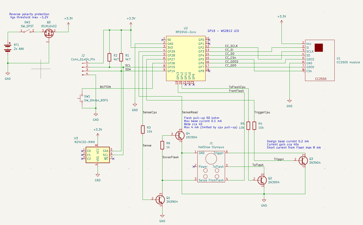
The low operating voltage also affects the user interface. LCDs, OLEDs, and most LED colors require higher voltages. However, red LEDs function adequately near 2 V, as they typically require approximately 1.8 V forward voltage. While red LEDs consume somewhat more current than higher-voltage alternatives, they provide excellent visibility.
I constructed a prototype receiver using a prototyping board and several meters of unshielded twisted pair (UTP) wire. While aesthetically unappealing and somewhat fragile, this approach required only one morning—considerably faster than designing a custom PCB and waiting for fabrication and delivery. The complete assembly fits within a Hammond 1593PGY enclosure, and I replaced the standard front panel with the "IR" translucent version to enable viewing of the red LED indicators.
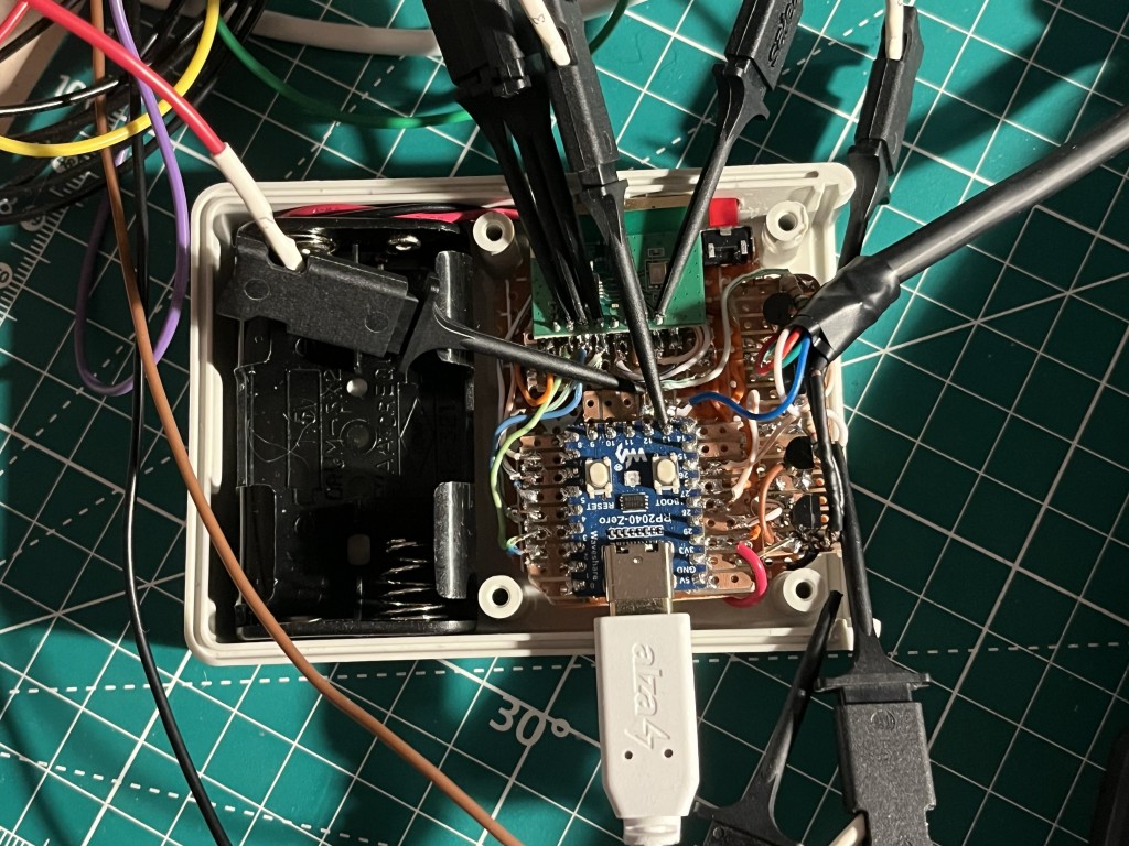
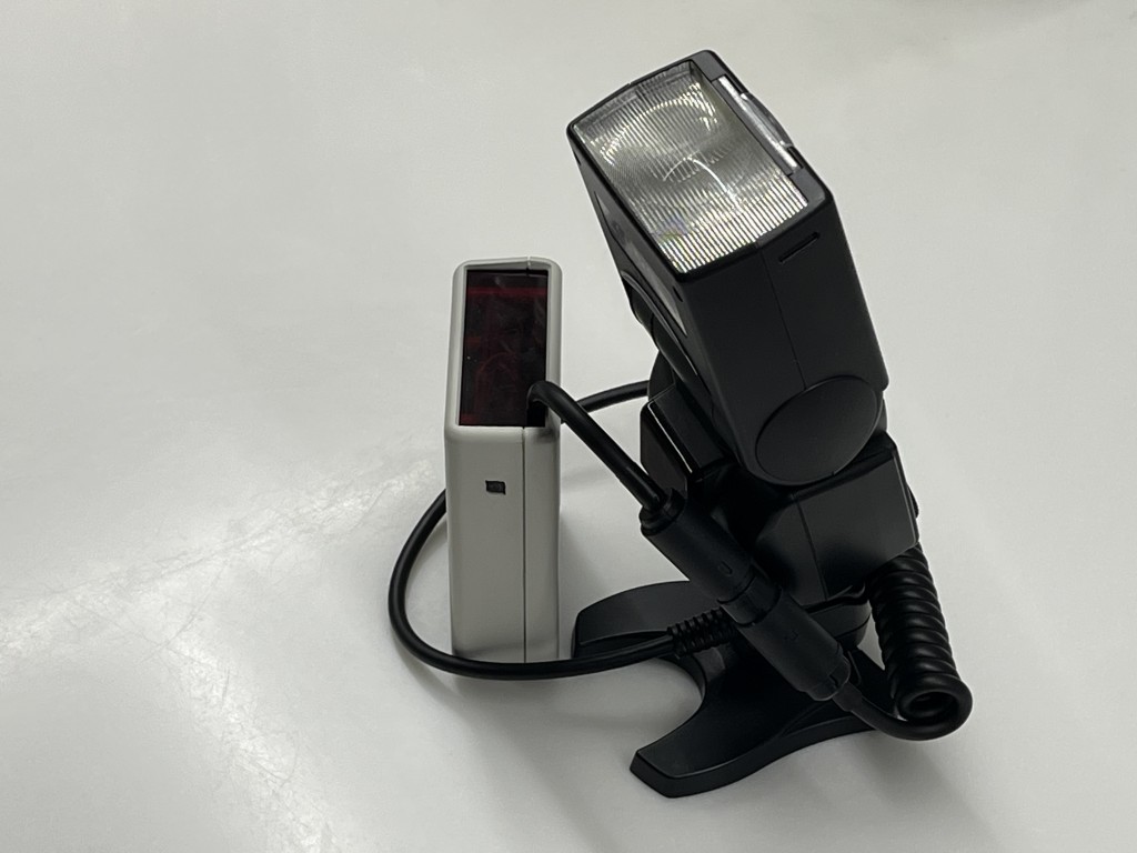
And this is how it looks when assembled and connected to the flash unit.
Firmware
The firmware’s primary function is translating between the Godox X protocol and the Olympus TTL protocol. This translation was largely straightforward, though several caveats exist, as described below.
I implemented the firmware in Rust. I may release it as open source once the final PCBs arrive, the user interface is complete, and the code is properly refactored.
Manual power control
Manual power control is straightforward. Whenever the receiver detects a manual power setting command (0xBC) from the Godox transmitter, I forward it to the flash using the Olympus 0x03 command. Power level translation uses the auto-detected maximum flash power (byte B1 from the 0x82 status response) and the known EV step sizes: 8 steps per EV for Olympus, 10 steps per EV for Godox.
TTL control
The primary challenge in TTL mode is selecting the correct Olympus command (0x02 versus 0x03) for setting power. The Godox transmitter uses the same command (0xB9) for both pre-flash and main flash power settings. My current implementation assumes two pre-flash triggers will occur and uses the 0x02 command until two trigger commands (0xB4 0x01) are received. After the second pre-flash trigger, I switch to the 0x03 command for the main flash until the quench command arrives (0xD5 0x21).
High-speed sync control
High-speed sync presents a significant challenge. The XProII (and likely other Godox transmitters) does not transmit shutter speed information to the flashes. However, Olympus speedlights require this information to calculate the appropriate maximum power level (and possibly to configure HSS pulse duration and repetition rate).
This issue remains unresolved.
Modeling lamp
I attempted to map the Godox modeling lamp control to the Olympus focus lamp. However, I have been unable to make this function work, despite believing I have identified the correct command. The FL-36R simply does not respond to it.
Missing features
Several features remain unimplemented. The two most significant are:
-
Godox transmitter ID: A transmitter configured with a specific ID does not synchronize with the receiver. I suspect the CC2500 sync bytes change based on the ID, but I have not yet investigated this.
-
Godox multi-flash mode: This mode enables capturing multiple exposures of a moving subject within a single frame.
Bloopers and dead ends
In the tradition of movie blooper reels during closing credits, here are some of my attempts that proved unproductive or incorrect.
Inspectrum
Even though I like Inspectrum when analyzing radio signals, it does not support the MSK modulation. So it gave me just another look at the spectrum.
Universal Radio Hacker
Universal Radio Hacker is another great tool, but again, no MSK support. And even with the data decoded by GNU Radio I had better luck using my shell and Python scripts.
Olympus E-30 TTL
The aging DSLR was not actually capturing properly exposed images when connected to the FL-36R in TTL mode via the extension cable. This baffles me; I must have overlooked something. However, I only discovered this issue after several days of testing, as it had not occurred to me to examine the actual photographs. The protocol recordings appeared correct—they simply always commanded full power.
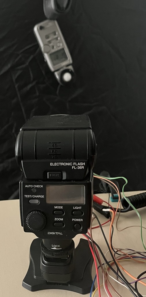
Flash power measurements
I spent several hours triggering the flash using the 0x03 command transmitted via Bus Pirate (using an SN74HC05N open-drain buffer for the CameraTx and Trigger signals) while recording pulse intensity with an older Sekonic flash meter.
I repeated these measurements while varying the subject distance.
The results were intriguing, but I could not determine the power level limits from this data reliably.
This was before I realized I could trigger the flash from the camera with the lens cap attached and correlate the measured power with the protocol bytes.
Equipment and tools used
Olympus cameras and speedlights
-
Olympus DSLR E-30
-
Olympus mirrorless E-M5 (mark I)
-
Olympus FL-36 speedlight
-
Olympus FL-36R speedlight
Godox transmitters and speedlights
-
Godox XproII transmitter
-
Godox X1T-S transmitter
-
Godox TT685II-O speedlight
Connecting cable
-
JJC FC-E3 off camera flash extension cord
Measuring and debugging equipment
Development boards and modules
Software tools
-
few custom Python scripts for manipulating data files